 |
Sensor
Description
|
Anyone who has operated a model train can tell you that the farther an engine gets from the transformer/track connection, the slower the engine runs due to voltage loss in the rails. I realized I could use this component of ohms law to design circuits that would allow a computer to "see" where trains were on the tracks. As an engine travels away from the power source, the voltage between the power source and the end of the rail steadily increases. This alone cannot be used to determine where the engine is on the track. The reason is that some engines use more current, or power, than others. Engines that use more power cause a larger voltage drop in the rails. That's why I also measure the current on each section of track. When you have both voltage and current measurements you can use a common electronic formula: E/I=R or voltage divided by current equals resistance. So if you know the resistance of the track per foot, you can determine how far the engine is from the power source.
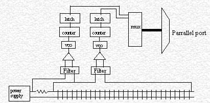
The real effort in this design was to create filter circuitry that could eliminate the abundant amount of electrical noise an engine makes as it clamors down those tracks making and breaking the electrical connection at a random frequency. Then there's the inductive kickback from the DC motor and the variable width 18 volt pulse from the PWM power supplies. The filter has to elimnate these undesired signals, yet still deliver the average millivolt levels to the op-amps to calculate voltage and current.
This design only allows for one engine on a section at a time, that's why I created 9 of these circuits and broke my track into 9 electrically isolated sections. Each of these sections must have perfect connections, hence every rail joint is soldered.
The accuracy of my sensors is 2 inches, this is due to the different pickup configurations in the engines. So I can't stop on a dime, I'll just have to settle for the silver dollar.